1. Introduction
ay by day all medical equipment are getting sophisticated, complex and expensive, rising the medical service charges. The basic nurse call system has become a luxury product for most of the economical hospitals. But it is a must have tool for patients, who are unable to move from their bed. Some scissor patient is not able to call someone loudly. Considering the balance between need and cost in this paper an economical nurse call system is developed. Nurse call system is not a new research topic. There has been lots of research going on developing low cost nurse call system. Like Design development and implementation of wireless nurse call station [1]. In this paper a simple one to one wireless communication has been defined. But in hospital scenario multiple patients call to an individual nurse station. For these type of communication tree network is best. In this research tree network is implemented. In some of the recent research Design and Implementation of Remote Medical Nursing Monitoring System based on Computer Network [2] is an internet dependent system.
But real-time critical system like this one cannot depend on internet connectivity. If internet is not available, the system still should provide the service of nurse calling. In the proposed system internet is not required. Although if user wants to monitor data from outside world an internet connection can be plugged in. In some of other researches like Nurse calls via personal wireless devices; some challenges and possible design solutions [3] discussed about wireless communication advantages but wireless devices needs to be portable also. In most of the conventional system calling device is fixed at a point where patient have to reach in order to call the nurse. In this implemented design each calling key fob is portable battery powered. So that if electricity goes out still the system can run itself on battery.
2. II.
3. Block Diagram of the System
Block diagram of the system is shown in fig. 1. There are several types of nodes in the system.
Base node is the call station. All data transfers to base node and from base node all data get uploaded to webserver. Base node can connect up to 6 child node simultaneously. But this does not limit its capability to control thousands of node at the same time. Here base node is connected with 5 wards. In each ward there can be several beds. Each bed is sending data to its corresponding ward node and each ward node is relaying the data to the base node. Base node has an RTC module to calculate the exact time of data receive. Whenever base node receives any data it updates webserver with the time stamp. Base node monitor, control, receive and transmits data to its child nodes. As the base node is unique in every network it most of the time hold zero as its address.
Child nodes are direct connected with base node. Number of child node is limited for a base node. Only five child node can be connected to a base node. If the network is larger than present one, then each base node can be treated as a child node to cover six times present number of patient. For this network each child node is treated as individual ward. And in a ward there can be several patient. Cabins are considered as individual bed. Each child node can be connected with a direct patients bed or to an expand node. A child node can be connected up to six expand node. Expand node is a sub node of each child node. Expand nodes are used to expand the number of bed node. For example, if any ward has thirty-six patients then one child will get connected to six expand node. And each expand node will have six bed node. So the number of expand needed to be used in a ward depends on the number of patient in that ward. Expand node mainly expand the network. The network is a tree network. In a tree network each expand node works as a branch in the network. And from that branch other branch can come out or any leaves can come out. Branch nodes relay the data from end node to its above branch. Above branch can be another expand node or child node. Expand node does not modify any data. Expand node is always in receiving mode. Whenever any end node transmits any data to expand node. It receives the data and transmits the data to its upper node only.
Bed nodes are end node. This node is used by each patient. In a ward there will be only two end node. One for call a patient from bed and another node is in toilet. For ward number of end node and number of bed node are equal. But as the toilet is common so one node will be at toilet. End node only transmits data. For simplicity there is only one type of call to the nurse. But a call from toilet & a call from bed is different. Whenever a patient presses a button from toilet it indicates an emergency alert. And when the alert is generated from room it indicates a normal call for assistance or medication etc. Each end node is battery powered. It helps a patient to move around in the room with the call button. End node stays in sleep mode most of the time in order to save power. Whenever a patient presses the button the end node wakes up from sleep mode and transmits the signal to its parent node.
4. III.
5. Circuit Analysis
Base node consists of several components. Among them Year 2016 ( )
6. Fig. 2: Circuit Diagram of Base Node
The heart of the system is Arduino uno board. Arduino uno board consists of a Atmega 328 microcontroller. Atmega328 is a 8bit micro-controller runs at 16Mhz clock speed. Arduino uno has only one SPI, one I2C & several GPIO. The Serial Peripheral Interface (SPI) bus is a synchronous serial communication interface specification used for short distance communication, primarily in embedded systems [4]. SPI communication is essential because both NRF wireless transmitter & Ethernet module uses it. So the MISO, MOSI, SCK pins are common for both the module but the slave select is different. To select NRF slave select pin is CE which is connected to digital pin 10 of Arduino. And to select Ethernet module as slave by digital pin 7. Both the serial clock is same. NRF uses IRQ pin for interrupt but it is not used in this scenario as base module does not require any power save option. Another important note NRF devices require 3.3v to operate [5]. Arduino board has a 3.3v voltage regulator onboard which is capable to power NRF. Ethernet module is also powered through Arduino board. RTC module communicates with microcontroller through I2C communication protocol. I²C (Inter-Integrated Circuit), is a multi-master, multi-slave, single-ended, serial computer bus [6]. SCL pin of rtc module is connected with SCL or Analog 5 no pin of Arduino uno and SDA pin of RTC module is connected with SDA/ Analog 4 pin of uno. RTC module is powered by 5V through Arduino. But rtc module requires a cr232 battery to keep the original time even it is not powered by uno. This battery can keep time tracking even for one year.
Each Child node consists of Arduino uno and one nrf transceiver. Child node & expander node is identical except the fact that child nodes communicate with base node directly. Other nodes like expander node consists of micro-controller and NRF24L01 transceiver. NRF transceiver works on free 2.4Ghz bandwidth. With this transceiver Arduino uno receives data from child node and transmits it to end node.
End node requires to be small in size and portable. So the micro-controller for end node are Arduino nano. The Arduino Nano is a small, complete, and breadboard-friendly board based on the ATmega328 [7]. Arduino nano can run on 3.3v and at end node there is only another device is connected which is NRF which also runs on 3.3v. So there is no 5v requires to run end node which is recommended for a long running portable node. To save power nano runs on sleep mode. Whenever user presses button to call nurse, nano wakes up from sleep and transmits the data to child node. And child node sends the data to base node. Nurse is notified through webserver with real time notification.
7. IV.
8. Hardware Implementation
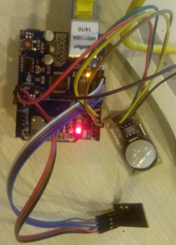
This project consists of four types of nodes but in hardware implementation the expansion module is not implemented. Here a small prototype is designed where other three nodes are implemented. First of all, base node. Year 2016 ( ) Fig. 3 : Implementation of Base Node Base node is powered by a +5v adapter. This node will be stationary on nurse call station. Ethernet shield is stackable with Arduino. Arduino is under Ethernet shield. From extra header other unused pins of Arduino can be accessed. Ethernet shield is connected with router through RJ45 cable. And router is capable of generating wifi hot spot. So, any nurse near wifi can access the server through their cell phone.
End node or bed node is powered by a 3.3v battery. Arduino nano has dedicated pins for battery connection as this device is for low power solution. A push button is used to call nurse. As the size of end node is small it can be packaged in a hand held module.
9. Conclusion
Nurse call system is an essential tool for every hospital. High cost nurse call system has far more facilities than this system. This system is designed considering the minimum requirement so that every hospital can afford a nurse call system. There are lots of improvement can be done in this system like nurse presence button. Adding blue code alert etc. This system is not suitable for any critical patient. For critical patient the system needs to be wired because it is possible to lose the wireless link. Although nrf auto reconnects if the wireless connection is lost. Additional circuitry can be added to implement an alert if any node is not found or lost. But all these features come with extra cost. This system fulfills the basic requirement for a general patient.
10. References Références Referencias