1. Introduction
owadays, vehicles are increased heavily and drivers, faces many problems in location identification and safety while driving vehicles. Mostly all the vehicle consists of GPS based navigation systems to identify the direction and way of path. But GPS signals are not available in tunnels, airports etc. For this, we substitute an RFID based location identification system to get the information continuously without break up.
The driver safety is built-up using wireless and sensor technologies [1]. RFID is rated as most promising transportation location system in VANETs, and other applied areas. Alternatively it can also be used to slow down the speed of vehicles by using Electronic Control Unit (ECU) in the place of school zones. 8051AT89S52 is used, since it is low cost when compared with 8051AT89C51. The car navigation and drowsiness detection system consists of three modules: RFID based Location Identification, Eye-ball detection, Hand pressure detection. RFID technology is used for drivers to get an automatic navigation guidance to identify the places and surrounding areas, and slows down the vehicle when school zones and speed breakers are detected. Eye-ball sensor are used to detect the sleepy state of driver by using NIR (Near infrared) sensor placed In spectacles to sense the eye-blink movement. If the blink is not debuted, sensor sends a signal to the microcontroller and buzzer turns on automatically, until driver presses reset button. Hand pressure sensors are used in this system which helps to detect the driver fatigue and drowsiness detection by detecting the hand pressure and force that is applied on the steering of a vehicle.
2. II.
3. Related Works
Our work is most likely related to two specific fields are Navigation assistance and Driver's drowsiness detection in VANET's. The current Navigation assistance system is obtaining information through GPS based devices installed in vehicles. But in practice, GPS not provided the exact information due to its low frequency positioning. And also GPS doesn't provide information about lane change direction, zones identification and the traffic updates. By using GPS signals are not available in tunnels, airports etc. Some of the research approaches presented in this paper was previously obtained [4], [6].This paper extends on those papers by providing:
? A motivating example for using the RFID technology to Navigation Assistance for VANETs. ? By using wei cheng et.al [4] proposed RFID-ANS method in our system, we get the exact information through RFID. ? Lane Level information and zones identification are adding advantages to our paper.
? By rewriting the tag information extended up to 128 Kbytes.
The RFID system consists of RFID tags and Readers. Read collision problem is mainly occurs while reading the tags when the vehicles moving fast [7], [9]. In our approach read collision is not possible and our design approach guarantee the RFID reader and tags are one-to-one coupling in an unauthorized areas. In the existing approaches for RFID in VANET's by fixing reader [8] on stationary and tags are deployed in vehicles. For example E-ZPass [11] using this method to collect the toll fee collection. Our approach is to deploy RFID in VANETs by fixing RFID tags on roads and RFID reader by placing in the bumper of vehicle for reading the tags accurately. The road beacon system, proposed [10], by using RFID tags that serves the traffic updates and road information. The numbers of major vehicle accidents are increasing day-to-day life because Year 2014 G of driver alertness and drowsiness. For this we make a driver safety system to monitor the physical actions of driver. Drowsiness detection mainly classified into ways ? Sensing of physiological characteristics.
? Monitoring the response from a driver.
We mainly concentrate on physiological actions of drivers by sensing the eye-blinking movement and the steering grip pressure. In our method, using a passive infrared sensor that is fixed on the spectacles of the driver to detect the eye-blinking. This method will immediately responds to the controller and makes alert to driver when there is no eye-blinking. The time delay fixed for IR sensors is "1" second or above to obtain a "blink event" rather than "Normal eye blinking". The driver operation is carried out by detecting the steering wheel movement of the driver. By using distributed sensor that are fixed like a wire winding on the steering to identify the pressure to state a driver action III.
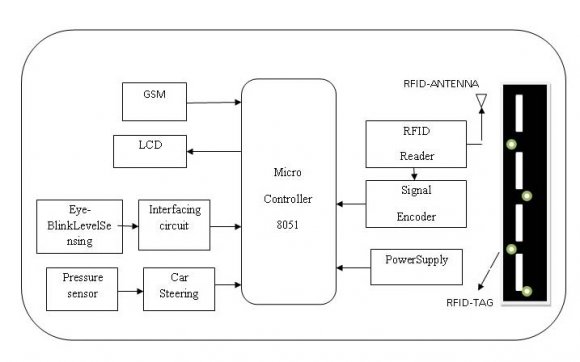
4. System Design
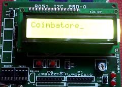
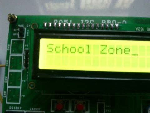
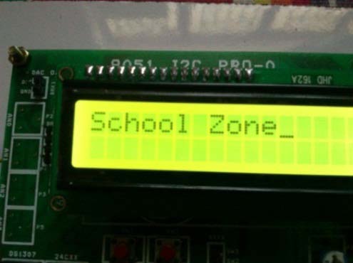
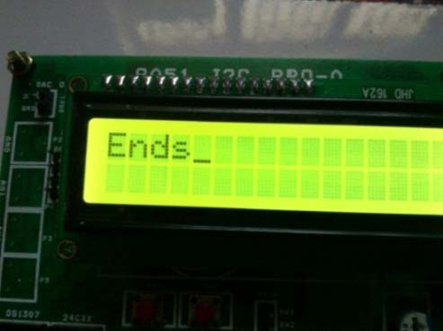
RFID system plays a major role to identifying places, zones and its surrounding areas. The main component of the RFID system is the reader and the tag. The RFID tags are separated into active and passive. Passive tags are cheaper because, it don't need any external power source. The RFID reader is located in bumper of the vehicle and the passive tags are deployed on the roads. When the vehicles enter near the corresponding places before 50 meters the reader detects and display the corresponding places [5]. If the vehicle enters near the school zone the corresponding tag will sends information to microcontroller and the relay slows down the vehicle speed until the same tag identified after the school zone ends.
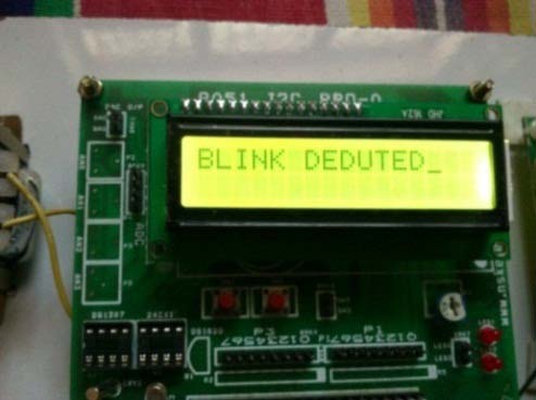
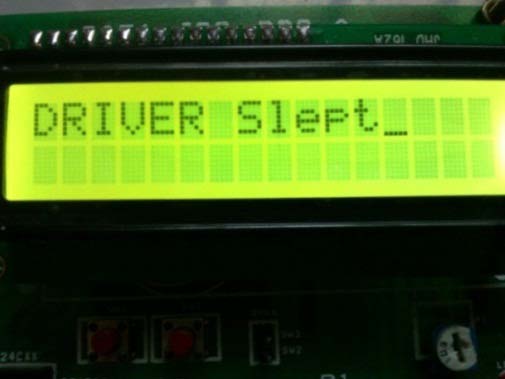
But it acts as a secondary control rather than driver control. The eye-blink sensor is to identify the eye movement of the driver and alerts when the eye closed for 4 seconds continuously. The near infrared waves used by sensors that are placed on the corner of the spectacle. It senses continuously and sends an "Eye blink debuted" message when it receives signal, Otherwise LED displays "Driver slept" message and buzzer turns on automatically until driver presses reset button.
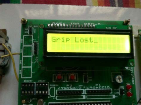
The pressure sensor is to detect the driver fatigue by using a chain of sensor units, each of them providing with capacitive sensing elements that measures grip force and hand position on the steering. In this system sensors will sends digital signal "1" and LED displays "Driver Normal" message when a normal pressure is present in the steering. If there is no pressure is present in the steering, it sends a digital signal "0" and "Grip lost" message is displayed and the buzzer turned on automatically until a normal pressure is applied on the steering. RFID is the technology, used in this system to update the location and zones. RFID system consists of RFID tags and RFID readers. Each RFID tags store the unique information, and RFID reader access the tag to collect the information through the wireless communication medium. In this system passive tags are used, hence there is no external power supply needed because it gets from reader itself.
5. a) Prototype Scheme
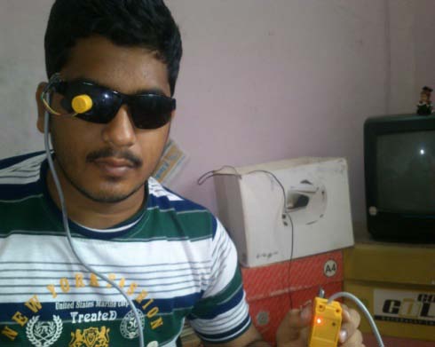
6. c) Eye Blink Sensor
The purpose of passive IR sensor is used to identify the driver sleepy state. Compared to Year 2014 G microwaves, the near infrared waves are passed to identify the static field depend on varying the amplitude and pressure. Based upon the oscillator frequency peak will vary depends upon blinking effect of eye movement. The DC output will vary depend upon the frequency, using the comparator switching effect will differs when eye lid is blinking and closed. The passive IR sensor is highly effective and doesn't cause any harmful effects to the human eye.
7. d) Pressure Sensor
The purpose of pressure sensor is to identify the driver fatigue detection. Compared to ultrasonic sensor, the circulated sensor identifies the measurement of grip force and hand position on the steering. The grip sensor will produces both digital and analog output to identify the state. The pressure sensor operates at 30 kHz frequency of 16 units based on capacitive sensing.
8. e) 8051 Microcontroller
AT89S52 series controller is an 8-bit controller. It is based on the architecture of highly optimized and is a very effective controller of embedded systems. It has an inbuilt 8-channel ADC. The memory space is the CODE segment, which executes the program, resides up to 64K. It is easily reprogramed and suitable for many embedded systems.
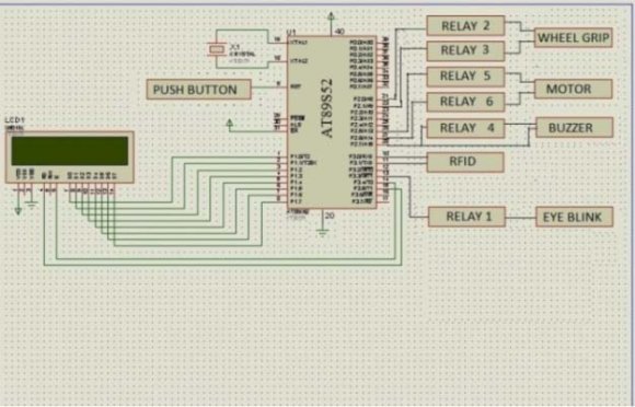
IV. The design and implementation of Location Identification and driver safety is done through the RFID and safety sensors. RFID consists of tag and reader. RFID reader is placed in the bumper of vehicle and passive tags are placed in the roads. The RFID tag has the EIC (Electronic Identification Code) which is unique. The EIC code is predefined in the controller is written in embedded c. The tag details are predefined in microcontroller. The driver identifies the places and zones according to message as per RFID [6] tag used. Earlier this process is used for automotive vehicles present in industries to carry goods to reach the destination [4]. The eye-blink module has input and output pin is connected to "P34" pin of the microcontroller. If any signals didn't received by the eyeblink sensor its sends information to the microcontroller and buzzer starts automatically. The pressure sensor [5] module has input and output pins and the output pin is connected to "P20" pin and "P21" of the microcontroller. The RFID Tx is connected to "P30" pin and "P31" is connected with controller port pin. RFID reader is used to interrogate a RFID tag. The reader has an antenna that emits radio waves, the tag responds the data to the reader and LCD displays the particular data. The first eight pins are connected to the LCD display to display the segments. The DC motor is connected to the "P25", "P26" pin of microcontroller to reduce the speed of vehicle by communicating with RFID reader when school zone is identified. Power supply is connected to 40 th pin of microcontroller and 20 th to ground. This gives the overall system design.
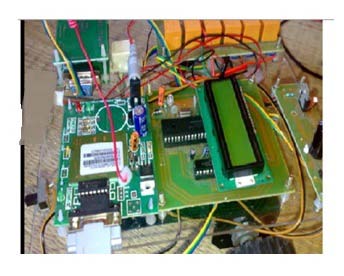
9. System Implementation
V.
10. Results And Discussion
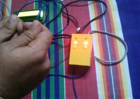
Figure 3 : shows the prototype of location identification and driver safety using RFID, eye-blink sensor and pressure sensor. This process is used to identify the location and driver safety during night hours. It is a self identifying device in a vehicle. In this method the RFID tags, RFID reader, Eye-blink sensor, Pressure sensor are used. 10 shows the grip sensor which will monitor grip pressure of the driver and leaves normally. Fig. 11 shows the prototype of grip lost and the buzzer turns on automatically until a particular pressure is present.
11. VI.
12. Conclusion
This work resolves the challenges in VANET, to identify the location and driver safety during driving vehicles. The experimental outcomes are very effective and can be easily carry out in real time. This can be extended by combining all those RFID and safety sensors to bring an effective communication and by GSM to update the traffic information. On the complete, this method proves to be very effective in Vehicular adhoc network environment.